Hardware · What has to implement it
More antennas, more paths
MIMO and MU-MIMO use multipath as a resource rather than a problem, and the antenna count in a device is a direct consequence.
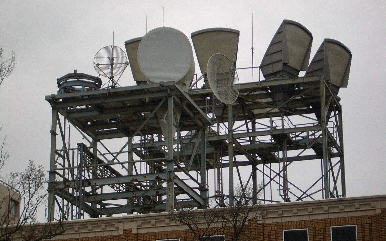
From obstacle to asset: how MIMO turned multipath propagation into a throughput multiplier — and why the antenna count on modern hardware is never accidental.
Multipath was the problem first
Early wireless engineers treated multipath propagation as interference. A signal bouncing off a wall, a ceiling, a person's shoulder arrived at the receiver slightly delayed, slightly out of phase, and slightly wrong. The receiver had to work around it. The insight that eventually rewrote antenna design was that those independent paths, given the right mathematics, could carry independent data simultaneously.
MIMO — Multiple Input, Multiple Output — encodes separate data streams onto separate antennas and relies on the fact that each stream travels a slightly different set of paths through space. The receiver, with its own array of antennas, samples the combined wavefront and applies linear algebra to pull the streams back apart. The channel itself becomes a matrix, and each antenna pair is a row in that matrix. Add antennas and you add rows; add rows and you increase the throughput available across a single radio channel.
IEEE 802.11n, ratified in 2009, was the first 802.11 amendment to standardise MIMO across the full product ecosystem — up to four spatial streams, each capable of independent data. Simultaneously, the LTE specification (3GPP Release 8, also 2009) introduced MIMO to cellular, with two- and four-antenna configurations specified from the start. Both standards used OFDM-based subcarrier structures precisely because OFDM's per-subcarrier narrowness makes the channel matrix well-behaved enough to invert cleanly.
Chronology
- 2009IEEE 802.11n ratified; MIMO enters mainstream Wi-Fi with up to 4 spatial streams
- 20093GPP Release 8 (LTE) introduces MIMO to cellular, 2×2 and 4×4 configurations
- 2016802.11ac Wave 2 adds downlink MU-MIMO, up to 4 simultaneous client streams
- 2019802.11ax (Wi-Fi 6) adds uplink MU-MIMO and couples it with OFDMA
- 20193GPP Release 15 (5G NR) specifies Massive MIMO with up to 128 active antenna elements
From single-user to multi-user
Single-user MIMO, for all its gains, wastes capacity: if a phone is small and can only fit two antennas, a four-stream access point runs two of its spatial streams idle when talking to that phone. MU-MIMO — Multi-User MIMO — addresses this by directing different spatial streams at different devices simultaneously. The access point uses beamforming weights to spatially separate the streams; each device sees mostly its own data, not its neighbour's.
Downlink MU-MIMO arrived in 802.11ac (Wi-Fi 5, Wave 2, 2016), allowing up to four simultaneous downlink streams to different clients. 802.11ax (Wi-Fi 6, 2019) added uplink MU-MIMO, a considerably harder problem because the access point must now coordinate transmissions from devices that cannot hear each other. Wi-Fi 6 also coupled MU-MIMO tightly with OFDMA, letting the scheduler allocate both spatial streams and frequency subcarriers simultaneously — filling the channel in two dimensions at once.
5G NR extended the same logic to what 3GPP calls Massive MIMO: base station arrays with 32, 64, or 128 active antenna elements, each independently phase-controlled. At those scales, the spatial multiplexing becomes genuine three-dimensional beamforming. A 3GPP Release 15 base station can serve dozens of UEs on the same time-frequency resource, separating them purely by spatial direction.
Antennas cost something
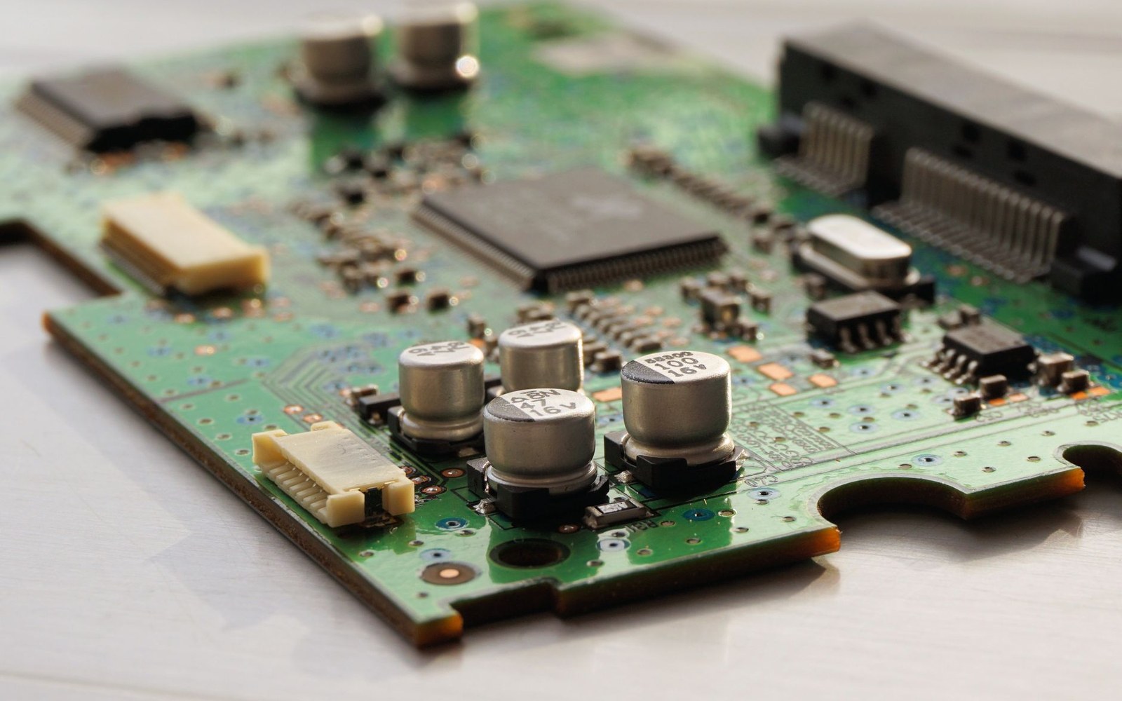
None of this is free in hardware. Each additional antenna requires its own RF front end: its own low-noise amplifier on receive, its own power amplifier on transmit, its own filter chain. In a handset, the physical envelope is fixed. Fitting four or eight LTE/NR antenna elements into a smartphone chassis, each with enough isolation from its neighbours to keep the spatial streams decorrelated, is an antenna placement problem that consumes significant engineering time. Antennas that are too close or oriented identically become correlated — they sample the same multipath, not different paths — and the matrix rank collapses, losing streams.
The result is that the antenna count printed in a router specification, or the "4×4 MIMO" on an access point's box, is a direct consequence of choices made at the standards table — in IEEE 802 working groups and 3GPP plenary sessions — filtered through the physics of isolation and the economics of RF front-end silicon. More antennas is never simply more antennas. It is more amplifiers, more filters, more switches, more calibration, and a harder layout problem — all justified because the mathematics of multipath genuinely delivers the throughput the standard promises.
MIMO — Multiple Input, Multiple Output — encodes separate data streams onto separate antennas and relies on the fact that each stream travels a slightly different set of paths through space.
Key relationships
- Spatial streams — independent data paths through the same channel; stream count bounded by min(Tx antennas, Rx antennas)
- Antenna isolation — physical separation or orientation required to keep streams decorrelated; collapse in rank costs streams
- OFDMA coupling — subcarrier assignment and spatial stream assignment combined in Wi-Fi 6/6E/7 and 5G NR scheduling
Also in Hardware
Read next
The rest of what has to implement it
- HardwareEverything between the antenna and the chipFilters, amplifiers and switches in the RF front end determine real performance more often than the baseband does, and they are band-specific.
- HardwareRadios designed to sleepBLE, Zigbee, Thread and LoRaWAN trade throughput for duty cycle, and each picked a different point on that curve for a stated reason.
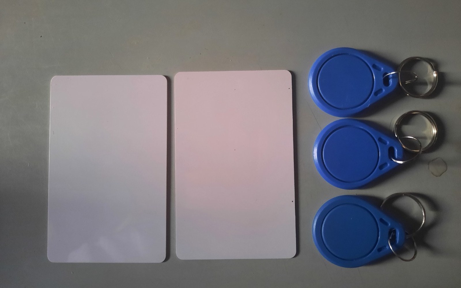 HardwarePower arriving through the antennaNFC and passive RFID draw their power from the reader's field, which is why range is measured in centimetres and why the tag can be a sticker.