Hardware · What has to implement it
Everything between the antenna and the chip
Filters, amplifiers and switches in the RF front end determine real performance more often than the baseband does, and they are band-specific.
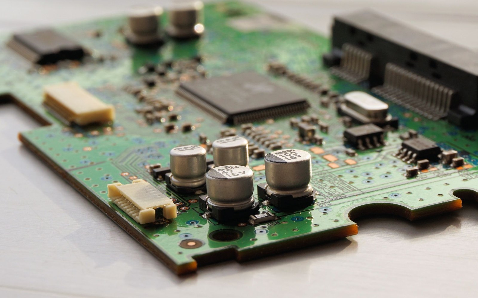
The overlooked layer that decides whether a radio actually works
The baseband processor gets the bylines. It runs the algorithms, implements the OFDMA scheduler, handles the cryptography, and carries the brand name on the die. But a signal that arrives at the antenna as a whisper of electromagnetic energy has to survive a considerable gauntlet before the baseband ever sees it — and that gauntlet is the RF front end: the filters, amplifiers, switches and impedance-matching networks that live between the antenna and the modem chip. They are analogue, they are band-specific, and they fail quietly rather than dramatically, which is why they tend to be invisible until something goes wrong.
What the front end actually contains
Every receive path begins with a low-noise amplifier, the LNA. Its job is to boost an incoming signal before noise from the rest of the chain can corrupt it. The figure of merit here is noise figure, measured in decibels — lower is better — and the LNA's noise figure dominates the receiver's sensitivity budget almost entirely. A modern LNA for a sub-6 GHz cellular band might achieve a noise figure below 1.5 dB; at mmWave frequencies the numbers worsen significantly, and the power consumption of the array required to compensate is one reason mmWave deployments have stayed closer to base stations than early 5G NR roadmaps implied.
On the transmit side the corresponding component is the power amplifier, the PA. It is also the component most likely to limit battery life on a phone or access point, because it converts DC power to RF with efficiency that depends sharply on how close to saturation it is running. Modern multicarrier waveforms — OFDM signals with high peak-to-average power ratios — force the PA to back off from saturation to maintain linearity, which reduces efficiency. Envelope tracking, a technique that varies the PA's supply voltage to match the instantaneous signal envelope, partially recovers that efficiency; it became standard in LTE-Advanced handsets and has carried forward into 5G designs.
Between the LNA and PA sit the filters, and filters are where band-specificity becomes structurally concrete. A receiver that accepts energy from the wrong part of the spectrum will be blinded by interference from adjacent services — cellular transmitters near Wi-Fi bands, GPS signals swamped by LTE uplink leakage, radar returns clobbering unlicensed 5 GHz devices. The dominant filter technology at these frequencies is bulk acoustic wave (BAW) for higher bands and surface acoustic wave (SAW) for lower ones. Both work by converting electrical signals into mechanical resonance in a piezoelectric material, which allows extremely sharp frequency selectivity in a package small enough to sit inside a phone. A single smartphone supporting a dozen or more LTE bands and two or three Wi-Fi bands may carry twenty or more discrete filter components — each tuned to a specific allocation, because physics does not permit a single filter to be retuned in software the way a baseband parameter can be.
Key components and what they do
- Low-noise amplifier (LNA) — first active element in the receive chain; noise figure here dominates receiver sensitivity
- Power amplifier (PA) — boosts the transmit signal; efficiency depends on signal waveform and back-off from saturation
- BAW filter — bulk acoustic wave resonator for bands above roughly 1.5 GHz; extremely selective, physically small
- SAW filter — surface acoustic wave resonator for lower bands; similar principle, lower cost, less suited to high frequencies
- Duplexer — paired filter allowing simultaneous transmit and receive on adjacent frequencies (FDD bands)
- Antenna switch — routes antenna connections to the correct chain; insertion loss directly hits link budget
- RF front-end module — integrated package combining switch, filters, LNA and PA from a single vendor
The antenna switch completes the quartet. Because a handset carries far fewer antennas than it does bands, a switch matrix routes any given antenna connection to the appropriate receive or transmit chain for the active band. In a carrier aggregation scenario — where 3GPP Release 10 and later allow a device to transmit and receive on multiple bands simultaneously — the switch architecture becomes a genuine combinatorial problem, and the insertion loss of the switch itself (the signal lost in passing through it) becomes a constraint on link budget. High-power-handling switch designs in silicon-on-insulator CMOS have largely displaced GaAs designs in the switch role, though GaAs and GaN retain dominance in the PA itself for their superior power density and efficiency.
Band-specificity is not a detail, it is the architecture
The reason the RF front end grows more complex with each generation of cellular or Wi-Fi is that bands are not interchangeable. The ITU divides spectrum allocations across three world regions, and national regulators then license specific bands within those regions in ways that diverge significantly. A device sold globally for 5G sub-6 GHz service may need to cover Band n77 (3.3–4.2 GHz), n78 (3.3–3.8 GHz), n79 (4.4–5.0 GHz), and a collection of sub-1 GHz bands for coverage — each requiring its own filter, and filter interactions with each other. Carrier aggregation combining two or more of these bands simultaneously demands that the transmitter's own signal not desensitise its own receiver — a problem called self-interference or desense — which requires either duplexers (for frequency-division duplex bands) or careful timing (for time-division duplex), along with additional isolation components.
Wi-Fi introduces its own layering. An 802.11ax (Wi-Fi 6) device operating in both the 2.4 GHz and 5 GHz bands needs separate filter and amplifier chains for each, because the propagation characteristics and the interference environment differ so substantially that a single design serves neither well. Wi-Fi 6E added the 6 GHz band — and with it a third front-end chain in devices that support all three. Wi-Fi 7's 320 MHz channels in 6 GHz place new demands on filter flatness across an unusually wide passband; a filter that introduces 1 dB of ripple across a 160 MHz channel is tolerable, but the same ripple profile across 320 MHz is not.
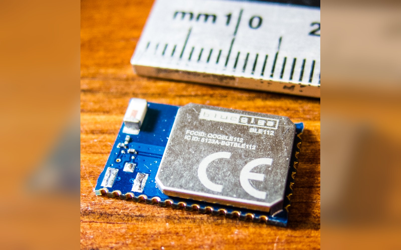
At the low-power edge — BLE, Zigbee, Thread — the front end shrinks to something closer to a single integrated receive/transmit block, often fabricated in the same CMOS process as the baseband. The duty-cycle discipline that makes these protocols power-efficient also relaxes the linearity requirements on the PA, since transmit events are brief and infrequent. But even here the filter matters: a BLE device in the 2.4 GHz ISM band shares spectrum with Wi-Fi and classic Bluetooth, and without adequate selectivity it will be blinded by a nearby 802.11n access point running a 40 MHz channel.
The hardware implementing all of this increasingly takes the form of RF front-end modules — integrated packages that combine switch, filter, LNA and PA in a single component from suppliers including Qorvo, Skyworks and Murata. Chipset vendors integrate more of the chain with each generation: Qualcomm's FastConnect series and MediaTek's Filogic line both push the front-end boundary closer to the antenna by absorbing more of the matching and switching logic into the main die. But the filters remain stubbornly discrete, because the physics of acoustic resonance does not integrate onto standard silicon. The boundary between chip and antenna is where materials science still sets the terms, and no amount of digital sophistication above that boundary can compensate for a front end that cannot keep unwanted energy out.
Because a handset carries far fewer antennas than it does bands, a switch matrix routes any given antenna connection to the appropriate receive or transmit chain for the active band.
Why band count compounds the problem
- Each licensed band requires its own acoustic filter, which cannot be software-reconfigured
- A global 5G handset may carry 20+ filter components
- Carrier aggregation adds self-interference constraints between transmit and receive paths
- Wi-Fi 6E and Wi-Fi 7 add a third (6 GHz) chain alongside 2.4 GHz and 5 GHz
- 320 MHz channel width in Wi-Fi 7 tightens filter flatness requirements significantly
Also in Hardware
Read next
The rest of what has to implement it
- HardwareMore antennas, more pathsMIMO and MU-MIMO use multipath as a resource rather than a problem, and the antenna count in a device is a direct consequence.
- HardwareRadios designed to sleepBLE, Zigbee, Thread and LoRaWAN trade throughput for duty cycle, and each picked a different point on that curve for a stated reason.
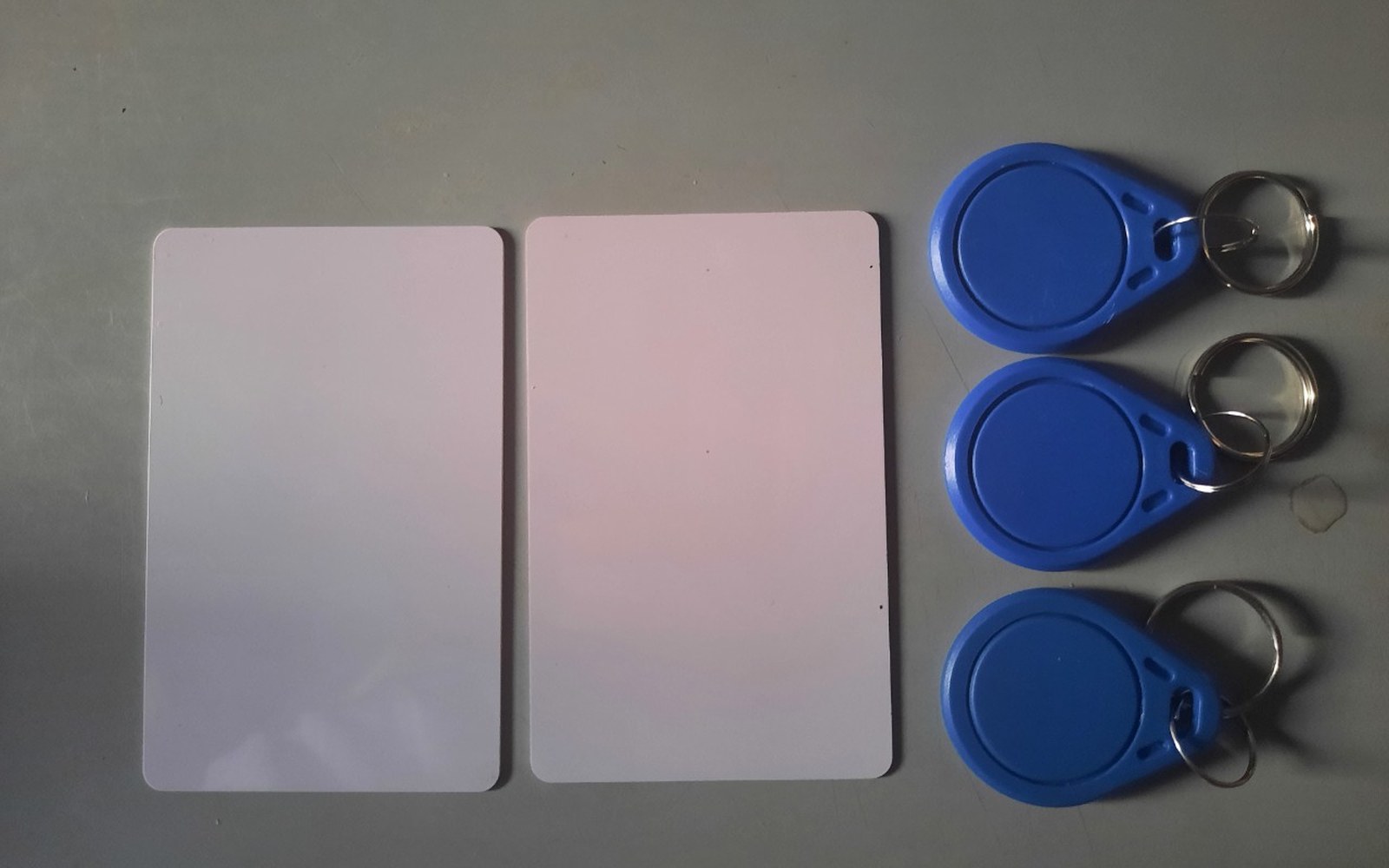 HardwarePower arriving through the antennaNFC and passive RFID draw their power from the reader's field, which is why range is measured in centimetres and why the tag can be a sticker.