Hardware · What has to implement it
Power arriving through the antenna
NFC and passive RFID draw their power from the reader's field, which is why range is measured in centimetres and why the tag can be a sticker.
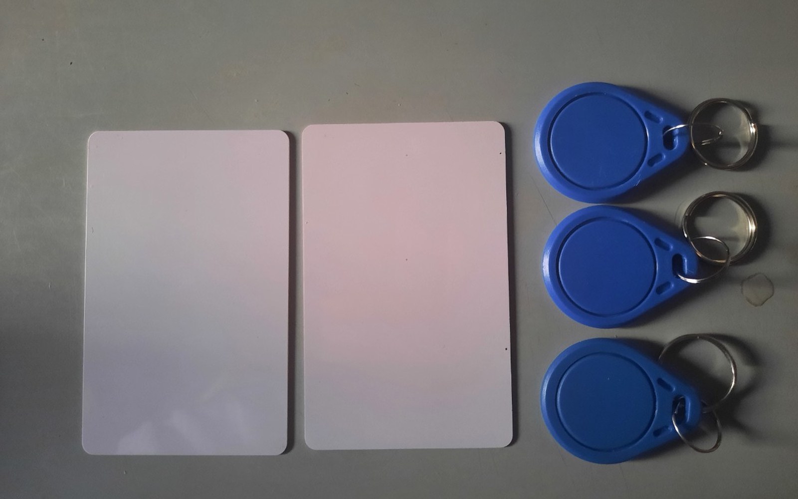
How a sticker becomes a circuit
A passive RFID tag contains no battery. It is, at the physical level, a coil of wire connected to a chip, printed or etched onto a substrate thin enough to laminate into a label. When a reader broadcasts an alternating field — at 125 kHz for legacy proximity cards, at 13.56 MHz for the ISO/IEC 14443 and ISO/IEC 15693 families that underpin modern NFC — that coil intercepts the field and the induced current rectifies to a small DC supply. The chip wakes, executes its logic, and modulates its response back to the reader by varying the load on the coil, a technique called backscatter modulation. The reader detects the impedance shift. No battery changed hands; no external power was consumed by the tag.
This is why range collapses so sharply. The magnetic field available to the tag falls with roughly the cube of distance from the reader's antenna in the near-field regime that both NFC and low-frequency RFID operate in. The ISO/IEC 14443 standard specifies a nominal read range of up to 10 centimetres, and real deployments — transit cards, contactless payment, phone tap-to-pair — sit comfortably inside that. UHF passive RFID, operating around 860–960 MHz under ISO/IEC 18000-63, shifts into far-field propagation and can reach several metres, but requires a larger antenna footprint and a reader that radiates meaningfully more power.
The RF front end on the reader side is where the engineering concentrates. The reader must generate a stable, clean carrier, detect the faint backscatter signal sitting on top of it, and suppress its own transmitted signal enough to resolve that return — a dynamic-range problem in miniature. On the tag side, the front end is the entire device: the matching network, the rectifier, and whatever energy-storage capacitance keeps the chip alive through a modulation dip. Mismatched tuning, even a detuned coil caused by proximity to metal, can cut harvested power by an order of magnitude, which is why NFC tags on metal objects require a ferrite spacer layer.
How passive power delivery works — key stages
- Reader broadcasts alternating field — at 13.56 MHz for NFC / ISO 14443
- Tag coil intercepts field — induced current rectified to DC supply
- Chip wakes and executes logic — no internal battery involved
- Tag modulates response — backscatter modulation varies coil load
- Reader detects impedance shift — recovers data from its own field
NFC adds a second mode — active peer-to-peer, where both devices carry their own power — but the tap-and-go use case that defined the technology's adoption is always the passive one, reader powering tag. The NFC Forum, which maintains the technical specifications above the ISO physical layer, formalised four tag types mapping to different ISO standards; NFC Forum tag type definitions govern what a certified device must read and write.
The achievement, understated by its ubiquity, is that a circuit sophisticated enough to hold a unique identifier, enforce a cryptographic handshake, or update a counter draws its entire operating power from a radio wave. The antenna is both the energy source and the communications channel.
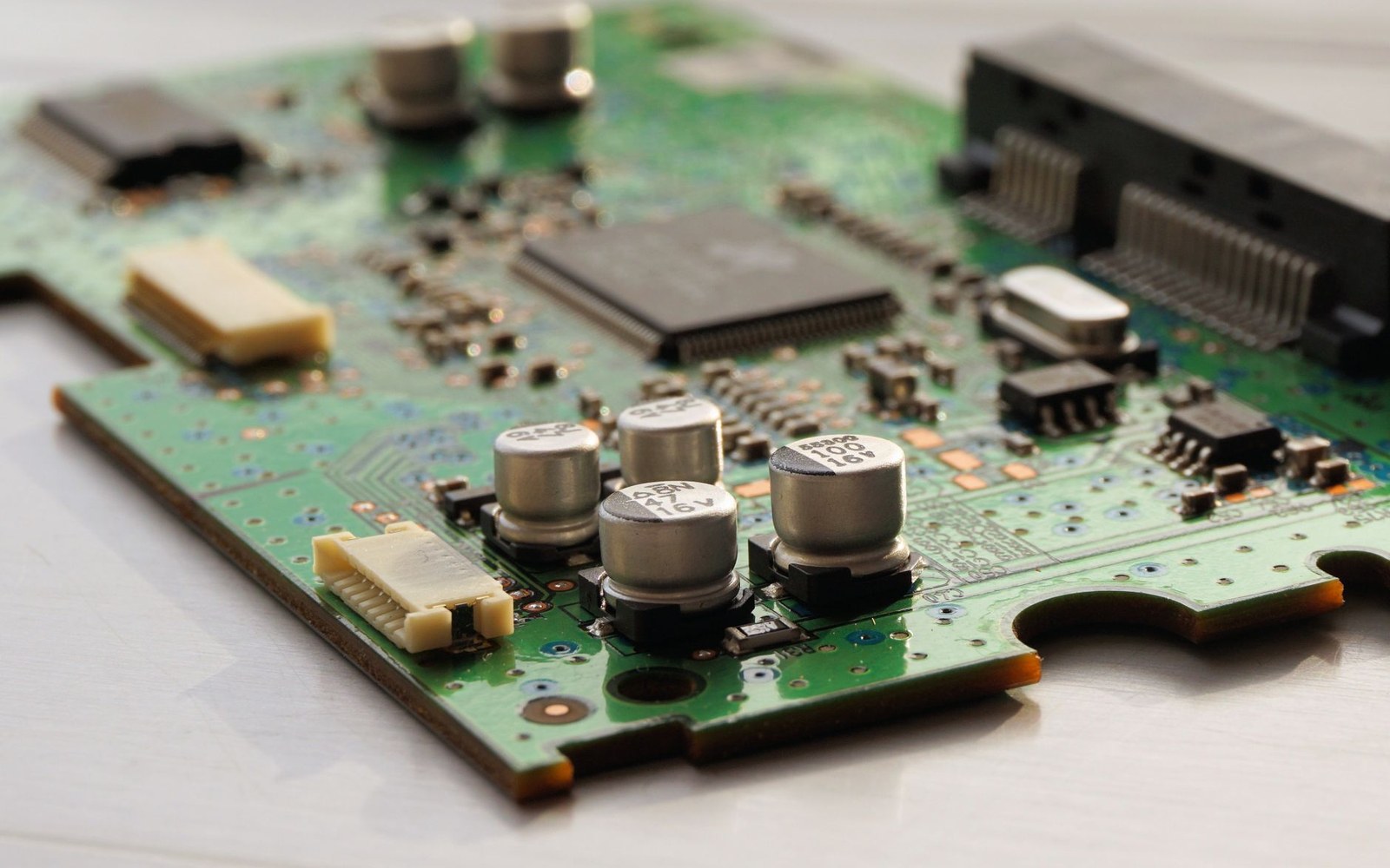
The ISO/IEC 14443 standard specifies a nominal read range of up to 10 centimetres, and real deployments — transit cards, contactless payment, phone tap-to-pair — sit comfortably inside that.
Frequency and range — reference figures
- 125 kHz — legacy proximity / access-control RFID; very short range
- 13.56 MHz — ISO/IEC 14443 (NFC, contactless payment); up to ~10 cm specified
- 860–960 MHz — UHF passive RFID (ISO/IEC 18000-63); up to several metres, larger antenna
Read next
The rest of what has to implement it
- HardwareEverything between the antenna and the chipFilters, amplifiers and switches in the RF front end determine real performance more often than the baseband does, and they are band-specific.
- HardwareMore antennas, more pathsMIMO and MU-MIMO use multipath as a resource rather than a problem, and the antenna count in a device is a direct consequence.
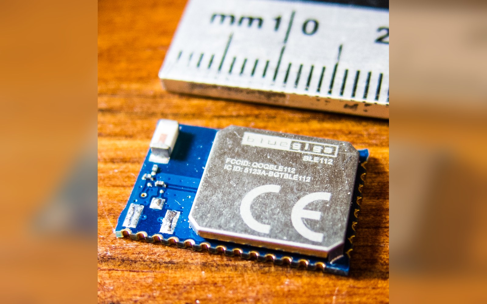 HardwareRadios designed to sleepBLE, Zigbee, Thread and LoRaWAN trade throughput for duty cycle, and each picked a different point on that curve for a stated reason.